
NBC 2016 –
- Wiring
In this section some guidelines are given in NBC 2016 which should be taken care while executing electrical work at site. These guidelines cover following topics –
6.1 Provision of maximum load
6.2 Selection of Sizes of Conductors
6.3 Branch Switches
6.4 Layout & installation Drawing
6.5 Conduits & Accessories
6.6 Joints & looping back
6.7 Passing through walls & floors
6.8 Wiring of Distribution Boards
6.9 PVC-Sheathed Wiring System
6.10 Conduit Wiring System
6.11 Cable Trunking /Cable ways
6.1 Provision of maximum load-
All conductors, switches and accessories shall be of such size as to be capable of carrying, without their respective ratings being exceeded, the maximum current which will normally flow through them.
6.1.1 – Estimation of Load Requirements –
In estimating the current to be carried by any contractor, the following ratings shall be taken, unless the actual values are known or specified for these elements. For this, refer table given below.
| S. No.
(1) |
Element
(2) |
Rating (W)
(3) |
| i) | Incandescent lamp | 60 |
| ii) | Ceiling Fan | 60 |
| iii) | Table fan | 60 |
| iv) | 6A Socket outlet | 100, unless the value of actual load is specified |
| v) | 16A Socket outlet | 100, unless the value of actual load is specified |
| vi) | Fluorescent Lamp:
Length: a) 600 mm b) 1200 mm c) 1500 mm |
25 50 90 |
| vii) | High Pressure Mercury Vapour (HPMV) lamps, High pressure sodium vapour (HPSV) lamps | According to their capacity, control gear losses shall be also considered as applicable |
| viii) | Compact fluorescent lamp (CFL) | 20 |
| ix) | Light emitting diode (LED) | 10 |
| x) | Exhaust fan | 50 |
| xi) | Geyser (storage type) | 2000 |
| xii) | Geyser (instant) | 3000 |
| xiii) | Computer point | 150 |
| xiv) | Computer (laptop) | 50 |
| xv) | Printer, laser | 1500 |
| xvi) | Printer, inkjet | 70 |
| xvii) | Kitchen outlet | 1500 |
| xviii) | Air conditioner: | |
| 1 TR | 1250 | |
| 1.5 TR | 1875 | |
| 2 TR | 2500 | |
| 2.5 TR | 3200 |
6.1.2 Electrical installation in a new building shall normally begin immediately on the commencement of the main structural building work and before finishing work such as plastering has begun except in the case of surface wiring which can be carried out after the plaster work. Following points should be taken care –
- The necessary conduits and ducts shall be positioned firmly by tying the conduit to the reinforcement before concreting.
- Care should be taken to avoid use of damaged conduit or ducts, the conduits end shall be given suitable anti-corrosive treatment and holes blocked off by putties or caps to protect conduits from getting blocked. All conduit openings and junction box openings, etc shall be properly protected against entry of mortar, concrete, etc, during construction.
6.2 Provision of maximum load-
- The size of conductors of circuits shall be so selected that the drop in voltage from consumer’s terminals in a public supply (or from the bus-bars of the main switchboard controlling the various circuits in a private generation plant) to any point on the installation does not exceed three percent of the voltage at the consumer’s terminals (or at two bus-bars as these may be) when the conductors are carrying the maximum current under the normal conditions of service.
- The overall voltage drop from the transformer end to consumer’s final distribution board shall not exceed six percent.
6.2.1 If the cable size is increased to reduce voltage drop in the circuit, the rating of the cable shall be sufficient to carry the current which the circuit is designed for.
In each circuit or sub-circuit the fuse/circuit-breaker shall be selected to match the current rating of the circuit to ensure the desired protection.
6.3 Branch Switches-
Where the supply is derived from a three-wire or four-wire source, and distribution is done on the two-wire system, all branch switches shall be placed in the outer or live conductor of the circuit and no single phase switch or protective device shall be inserted in the middle wire, earth or earthed neutral conductor of the circuit. Single-pole switches (other than for multiple control) carrying not more than 16 A may be of tumbler type or flush type which shall be on when the handle or knob is down.
6.4 Layout & Installation Drawing-
6.4.1 The electrical layout should be drawn indicating properly the locations of all outlets, such as, lamps, fans, appliances (both fixed and movable) and motors and best suit for wiring.
6.4.2 All runs of wiring and the exact positions of all points of switch-boxes and other outlets shall be first marked on the plans of the building and approved by the Engineer-in-Charge or the owner before actual commencement of the work.
6.4.3 Industrial layout drawings should indicate the relative civil and mechanical details.
6.4.4 Layout of Wiring
The layout of wiring should be designed keeping in view disposition of the lighting system to meet the illumination levels. All wirings shall be done on the distribution system with main and branch distribution boards at convenient physical and electrical load centres. All types of wiring, whether concealed or unconcealed should be as near the ceiling as possible. In all types of wirings due consideration shall be given for neatness and good appearance.
6.4.5 Balancing of circuits in three-wire or poly-phase installation shall be arranged beforehand. Proper balancing can be done only under actual load conditions. Conductors shall be so enclosed in earthed metal or incombustible insulating material that it is not possible to have ready access to them. Means of access shall be marked to indicate the voltage present. Where terminals or other fixed live parts between which a voltage exceeding 250 V exists are housed in separate enclosures or items of apparatus which, although separated are within reach of each other, a notice shall be placed in such a position that anyone gaining access to live parts is warned of the magnitude of the voltage that exists between them. Where loads are single phase, balancing should be for the peak load condition based on equipment usage. Facility for change should be built into the distribution design.
6.5 Conduits & Accessories –
6.5.1 – Conductors
Conductors for all the internal wiring shall be of copper Conductors for power and lighting circuits shall be of adequate size to carry the designed circuit load without exceeding the permissible thermal limits for the insulation. For final section wiring to larger loads, the current carrying capacity will preside. The conductor size shall also be based on the voltage drop in the line so as to provide a terminal voltage not below the prescribed voltage requirement.
The conductor for final sub-circuit for fan and light wiring shall have a nominal cross-sectional area not less than 1.50 mm2 copper. The cross-sectional area of conductor for power wiring shall be not less than 2.5 mm2 copper. The minimum cross-sectional area of conductor of flexible cord shall be 1.50 mm2 copper.
In existing buildings where aluminum wiring has been used for internal electrification, changeover from aluminum conductor cables to copper conductor cables is recommended as it has been found that aluminum conductors below 10 mm2 size pose a number of hazards.
(NOTE . It is advisable to replace wiring, which is more than 30 years old as the insulation also would have deteriorated, and will be in a state to cause failure on the slightest of mechanical or electrical disturbance.)
6.5.2 – Flexible cables & flexible cords –
Flexible cables and cords shall be of copper and stranded and protected by flexible conduits or tough rubber or PVC sheath to prevent mechanical damage.
6.5.3 Cable Ends –
When a stranded conductor having a nominal sectional area less than 6 mm2 is not provided with cable sockets, all strands at the exposed ends of the cable shall be soldered together or crimped using suitable sleeve or ferrules.
6.5.4 Special Risk-
Special forms of construction, such as flame proof enclosures, shall be adopted where there is risk of fire or explosion.
6.5.5 Connection to Ancillary Building –
Unless otherwise specified, electric connections to ancillary buildings, such as out-houses, garages, etc, adjacent to the main building and when no roadway intervenes shall be taken in an earthed GI pipe or heavy duty PVC or HDPE pipe of suitable size. This pipe can be taken either underground or over ground, however, in latter case, its height from the ground shall not be less than 5.8 m. This applies to both runs of mains or sub-mains or final sub-circuit wiring between the buildings.
6.5.6. Expansion Joints
Distribution boards shall be so located that the conduits shall not normally be required to cross expansion joints in a building. Where such crossing is found to be unavoidable, special care shall be taken to ensure that the conduit runs and wiring are not in any way put to strain or damaged due to expansion of building structure. Anyone of the following standard methods of connection at a structural expansion joint shall be followed:
- a) Flexible conduit shall be inserted at place of expansion joint.
- b) Oversized conduit overlapping the conduit.
- c) Expansion box.
Supports and flexible joints shall be of same requirement as the rising main/bus duct in so far as resistance to seismic forces is concerned. This is further important when rising mains and bus-ducts cross expansion joints.
6.5.7 Low Voltage (Types of wires/cables)
Low voltage services utilizes various categories of cables/wires, such as fibreoptic cable, co-axial, category cable, etc. These shall be laid at least at a distance of 300 m from any power wire or cable. The distance may be reduced only by using completely closed earthed metal trunking with metal separations for various kind of cable. Special care shall be taken to ensure that the conduit runs and wiring are laid properly for low voltage signal to flow through it.
The power cable and the signal or data cable may run together under floor and near the equipment. However, separation may be required from the insulation aspect, if the signal cable is running close to an un-insulated conductor carrying power at high voltage. All types of signal cables are required to have insulation level for withstanding 2 kV impulse voltage even if they are meant for service at low voltage.
6.6 Joints & Looping back –
6.6.1 Where looping back system of wiring is specified, the wiring shall be done without any junction or connector boxes on the line. Where joint box system is specified, all joints in conductors shall be made by means of suitable mechanical connectors in suitable joint boxes. Whenever practicable, only one system shall be adopted for a building, preferably a looping back system.
6.6.2 In any system of wiring, no bare or twist joints shall be made at intermediate points in the through run of cables unless the length of a final sub-circuit, sub-main or main is more than the length of the standard coil as given by the manufacturer of the cable. If any jointing becomes unavoidable such joint shall be made through proper cut-outs or through proper junction boxes open to easy inspection, but in looping back system no such junction boxes shall be allowed.
6.6.3 Joints are a source of problems in reliability and are also vulnerable to fire. They should be avoided or at least minimized. They should under no circumstance
exceed more than one to two in total length and distance between two shall not be less than 5 m. Joint should not be used as tap-off for multiple feeders. Where joints in cable conductors or bare conductors are necessary, they shall be technically and electrically sound. Joints in non-flexible cables shall be accessible for inspection; provided that this requirement shall not apply to joints in cables buried underground, or joints buried or enclosed in non-combustible building materials. Joints in non-flexible cables shall be made by soldering, brazing, welding or mechanical clamps, or be of the compression type; provided that mechanical clamps shall not be used for inaccessible joints buried or enclosed in the building structure. All mechanical clamps and compression type sockets shall securely retain all the wires of the conductors. Any joint in a flexible cable or flexible cord shall be effected by means of a cable coupler.
For flexible cables for small loads less than 1 kW, while it is desirable to avoid joints, if unavoidable, joints may be made either by splicing by a recognized method or by using a connector and protecting the joint by suitable insulating tape or sleeve or straight joint. For application of flexible cable for loads of 1 kW or more, if joint is unavoidable, crimped joint is preferred. Spliced joint should not be used for large loads.
There are different standard joints, such as epoxy resin based joint, heat shrinkable plastic sleeve joint, etc, and each one has its advantage and disadvantage. Selection has to be made on the basis of application, site conditions and availability of skilled licensed workmen trained in the application of the particular type of joint.
6.6.4 Every joint in a cable shall be provided with insulation not less effective than that of the cable cores and shall be protected against moisture and mechanical damage. Soldering fluxes which remain acidic or corrosive at the completion of the soldering operation shall not be used.
For joints in paper-insulated metal-sheathed cables, a wiped metal sleeve or joint box, filled with insulating compound, shall be provided.
Where an aluminum conductor and a copper conductor are joined together, precautions shall be taken against corrosion and mechanical damage to the conductors.
6.6.5 Pull at Joints and Terminals
Every connection at a cable termination shall be made by means of a terminal, soldering socket, or compression type socket and shall securely contain and anchor all the wires of the conductor, and shall not impose any appreciable mechanical strain on the terminal or socket.
Flexible cords shall be so connected to devices and to fittings that tension is not transmitted to joints or terminal screws. This shall be accomplished by a knot in the cord, by winding with tape, by a special fitting designed for that purpose, or by other approved means which can prevent a pull on the cord from being directly transmitted to joints or terminal screws.
6.7 Passing Through Walls & Floors
walls, care shall be taken to see that wires/cables pass freely through protective pipe or box and that the wires pass through in a straight line without any twist or cross in wires.
One of the following methods shall be employed for laying wires/cables:
a) Conduit wiring system (see 6.10) . The conductor shall be carried either in a rigid steel conduit or a rigid non-metallic conduit conforming to accepted standards [8-2(33)].
The conduits shall be colour coded as per the purpose of wire carried in the same. The recommended colour coding may be in form of bands of colour (100 mm thick, with centre to centre distance of 300 mm) or coloured throughout. The colour scheme may be as follows:
Conduit Type Colour Scheme
Power conduit Black
Security conduit Blue
Fire alarm conduit Red
Low voltage conduit Brown
UPS conduit Green
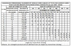
Conduit wiring system shall comply with accepted standards [8-2(34)]. The number of insulated conductors that can be drawn into rigid conduit is given in Tables 1 (see Table 1A for rigid steel conduits and Table 1B for rigid non-metallic conduits).
b) Cable trunking/cable ways (see 6.11) . Cable trunking/cable ways system should be used when number of wires/small cable sizes to be laid is more than the conduit capacity. Care should be taken to have space in the trunking
system to minimize heating of wires and to provide identification of the different circuits. Cable trunking or ducting system shall comply with accepted standards [8-2(35)].
c)Tray and ladder rack .
As tray provides continuous support, unless mounted on edge or in vertical runs (when adequate strapping or clipping is essential), the mechanical strength of supported cable is not as important as with ladder-racking or structural support methods. Consequently, tray is eminently suitable for the smaller unarmoured cabling while ladder racks call for armoured cables or larger unarmoured cables as they provide the necessary strength to avoid sagging between supports. Both tray and ladder racks are provided with accessories to facilitate changes of route, and they provide no difficulty in this respect on vertical runs.
Cable tray/ladder racks and support systems shall be installed in such a way that the deflection between the spans shall be less than 1 percent of the span.
Power cables running in cable ladders both horizontal and vertical shall be fixed with proper clamps which can withstand the mechanical force created on the cable in case of short circuit current. The complete installation consisting of cables, ladders, clamps, ladder supports and fixtures shall also withstand the mechanical force of short circuit current. Only one layer of power cable shall be laid in a ladder. The minimum space between two cables shall be equal to the diameter of the biggest cable. Cable tray and ladder system shall comply with IEC 61537:2006 ‘Cable management – Cable tray systems and cable ladder systems’ (under publication as an adopted Indian Standard).
6.7.2 Insulated conductors while passing through floors shall be protected from mechanical injury by means of rigid steel/non-metal conduit or by mechanical protection up to a height not less than 1.5 m above the floor and flush with the ceiling below. These steel conduits shall be earthed and securely bushed.
Power outlets and wiring in the floor shall be generally avoided. If not avoidable, false floor trunking or metal floor trunking should be used. Power sockets of adequate IP/IK rating shall be used.
False floor shall be provided where density of equipment and interconnection between different pieces of equipment is high. Examples are, mainframe computer station, telecommunication switch rooms, etc. Floor trunking shall be used in large halls, convention centres, open plan offices, laboratory, etc.
In case of floor trunking, drain points/weep holes shall be provided within the trunking for installation for conventional centres, exhibition areas or any other place where water may spill into the trunking, as there might be possibility of water seepage in the case of wiring passing through the floors. Proper care should be taken for providing suitable means of draining of water. Possibility of water entry exists from floor washing, condensation in some particular weather and indoor temperature conditions. At the design stage, these aspects shall be assessed and an appropriate means of avoiding, or reducing, and draining method shall be built in. Floor trunking outlets shall be suitably IP rated for protection against dust and water.
Floor outlet boxes are generally provided for the use of appliances, which require a signal, or communication connection. The floor box and trunking system should
cater to serve both power distribution and the signal distribution, with appropriate safety and non-interference.
6.7.3 Where a wall tube passes outside a building so as to be exposed to weather, the outer end shall be bell-mouthed and turned downwards and properly bushed on the open end.
6.8 Wiring of Distribution Boards
6.8.1 All connections between pieces of apparatus or between apparatus and terminals on a board shall be neatly arranged in a definite sequence, following the
arrangements of the apparatus mounted thereon, avoiding unnecessary crossings.
6.8.2 Cables shall be connected to a terminal only by soldered or welded or crimped lugs using suitable sleeve, lugs or ferrules unless the terminal is of such a
form that it is possible to securely clamp them without the cutting away of cables stands. Cables in each circuit shall be bunched together.
6.8.3 All bare conductors shall be rigidly fixed in such a manner that a clearance of at least 25 mm is maintained between conductors or opposite polarity or other than insulation material.
6.8.4 If required, a pilot lamp shall be fixed and connected through an independent single pole switch and fuse to the bus-bars of the board. Leads connecting bus-bars to any instrument or indicating lamp or an outgoing connection switch or breaker face the same fault current that is applicable to the bus-bar and as such should be provided with a fuse capable of handling the prospective fault current.
6.8.5 In a hinged type board, the incoming and outgoing cables shall be fixed at one or more points according to the number of cables on the back of the board leaving suitable space in between cables, and shall also, if possible, be fixed at the corresponding points on the switchboard panel. The cables between these points
shall be of such length as to allow the switchboard panel to swing through an angle of not less than 90° and cables arranged and clamped in such a manner that the cables do not face bending, but only face a twist, when the hinged door is opened. The circuit breakers in such cases shall be accessible without opening the door of distribution board. Also, circuit breakers or any other equipment (having cable size more than 1.5 mm2 multi- strand wire) shall not be mounted on the door.
NOTE . Use of hinged type boards is discouraged, as these boards lead to deterioration of the cables in the hinged portion, leading to failures or even fire.
6.8.6 Wires terminating and originating from the protective devices shall be properly lugged and taped.
6.9 PVC-Sheathed Wiring System
6.9.1 General
Wiring with PVC-sheathed cables may be used for temporary installations for medium voltage installation and may be installed directly under exposed conditions of sun and rain or damp places.
6.9.2 PVC Clamps/PVC Channel
The clamps shall be used for temporary installations of 1-3 sheathed wires only. The clamps shall be fixed on wall at intervals of 100 mm in the case of horizontal runs and 150 mm in the case of vertical runs.
PVC channel shall be used for temporary installations in case more than 3 wires or wires or unsheathed wires. The channel shall be clamped on wall at intervals not exceeding 300 mm. PVC clamps/PVC channel shall conform to accepted standards.
6.9.3 Protection of PVC-Sheathed Wiring from Mechanical Damage
a) In cases where there are chances of any damage to the wirings, such wirings shall be the base of which is made flush with the plaster or brickwork, as the case may be, or the wiring shall be drawn through a conduit complying with all requirements of conduit wiring system (see 6.10).
b) Such protective coverings shall in all cases be fitted on all down-drops within 1.5 m from the floor.
6.9.4 Bends in Wiring
The wiring shall not in any circumstances be bent so as to form a right angle but shall be rounded off at the corners to a radius not less than six times the overall diameter of the cable.
6.9.5 Passing Through Floors
All cables taken through floors shall be enclosed in an insulated heavy gauge steel conduit extending 1.5 m above the floor and flush with the ceiling below, or by means of any other approved type of metallic covering. The ends of all conduits or pipes shall be neatly bushed with porcelain, wood or other approved material.
6.9.6 Passing Through Walls
The method to be adopted shall be according to good practice. There shall be one or more conduits of adequate size to carry the conductors [see 6.10.1(a)]. The conduits shall be neatly arranged so that the cables enter them straight without bending.
6.9.7 Stripping of Outer Covering
While cutting and stripping of the outer covering of the cables, care shall be taken that the sharp edge of the cutting instrument does not touch the rubber or PVC-sheathed insulation of conductors. The protective outer covering of the cables shall be stripped off near connecting terminals, and this protective covering shall
be maintained up to the close proximity of connecting terminals as far as practicable. Care shall be taken to avoid hammering on link clips with any metal instruments, after the cables are laid. Where junction boxes are provided, they shall be made moisture-proof with an approved plastic compound.
6.9.8 Painting
If so required, the tough rubber-sheathed wiring shall, after erection, be painted with one coat of oil-less paint or distemper of suitable color over a coat of oil-less primer, and the PVC-sheathed wiring shall be painted with a synthetic enamel paint of quick drying type.
6.10 Conduit Wiring System
Conduit wiring system shall comply with accepted standards [8-2(34)]. Requirements relating to conduit wiring system with rigid steel and non-metallic conduits shall be as per 6.10.1 to 6.10.3.
6.10.1 Surface Conduit Wiring System with Rigid Steel Conduits
- a) Type and size of conduit – All conduit pipes shall conform to accepted standards [8-2(36)], finished with galvanized or enamelled surface. All conduit accessories shall be of threaded type and under no circumstance pin grip type or clamp type accessories be used. No steel conduit less than 16 mm in diameter shall be used. The number of insulated conductors that can be drawn into rigid steel conduit is given in Tables 1A.
TABLE 1A
NOTES
1 The table shows the maximum capacity of conduits for the simultaneously drawing of cables. The columns headed S apply to runs of conduit which have distance not exceeding 4.25 m between draw-in boxes, and which do not deflect from the straight by an angle of more than 15°. The columns headed B apply to runs of conduit which deflect from the straight by an angle of more than 15°.
2 In case an inspection type draw-in box has been provided and if the cable is first drawn through one straight conduit, then through the draw-in box, and then through the second straight conduit, such systems may be considered as that of a straight conduit even if the conduit deflects through the straight by more than 15°.
3 Conductor sizes for cables and wires above and including 2.5 mm2 core size shall be multi-stranded.
1) For copper conductors only.
2) For aluminum conductors only.
b) Bunching of cables – Unless otherwise specified, insulated conductors of a.c. supply and d.c. supply shall be bunched in separate conduits. For lighting and small power outlet circuits phase segregation in separate conduits is recommended.
c) Conduit joints – Conduit pipes shall be joined by means of screwed couplers and screwed accessories only [see 8-2(37)]. In long distance straight runs of conduit, inspection type couplers at reasonable intervals shall be provided or running threads with couplers and jam-nuts (in the latter case the bare threaded portion shall be treated with anti-corrosive preservative) shall be provided. Threaded on conduit pipes in all cases shall be between 11 mm and 27 mm long sufficient to accommodate pipes to full threaded portion of couplers or accessories. Cut ends of conduit pipes shall have no sharp edges or any burrs left to avoid damage to the insulation of conductors while pulling them through such pipes.
d) Protection against dampness – In order to minimize condensation or sweating inside the tube, all outlets of conduit system shall be properly drained and ventilated, but in such a manner as to prevent the entry of insects as far as possible.
e) Protection of conduit against rust – The outer surface of the conduit pipes, including all bends, unions, tees, conduit system shall be adequately protected against rust particularly when such system is exposed to weather. In all cases, no bare threaded portion of conduit pipe shall be allowed unless such bare threaded portion is treated with anti-corrosive preservative or covered with suitable plastic compound.
f) Fixing of conduit – Conduit pipes shall be fixed by heavy gauge saddles, secured to suitable wood plugs or other plugs with screws in an approved manner at an interval of not more than 1 m, but on either side of couplers or bends or similar fittings, saddles shall be fixed at a distance of 300 mm from the centre of such fittings. Conduit fittings shall be avoided as far as possible on conduit system exposed to weather; where necessary, solid type fittings shall be used.
g) Bends in conduit – All necessary bends in the system including diversion shall be done by bending pipes; or by inserting suitable solid or inspection type normal bends, elbows or similar fittings; or fixing cast iron, thermoplastic or thermosetting plastic material inspection boxes, whichever is more suitable. Radius of such bends in conduit pipes shall be not less than 75 mm. No length of conduit shall have more than the equivalent of four quarter bends from outlet to outlet, the bends at the outlets not being counted.
h) Outlets – All outlets for fittings, switches, etc, shall be boxes of suitable metal or any other approved outlet boxes for either surface mounting or flush mounting system.
j) Conductors – All conductors used in conduit wiring shall preferably be stranded. No single-core cable of nominal cross-sectional area greater than 130 mm2 enclosed along in a conduit and used for alternating current.
k) Erection and earthing of conduit – The conduit of each circuit or section shall be completed before conductors are drawn in. The entire system of conduit after erection shall be tested for mechanical and electrical continuity throughout and permanently connected to earth conforming to the requirements as already specified by means of suitable earthing clamp efficiently fastened to conduit pipe in a workman like manner for a perfect continuity between each wire and conduit. Gas or water pipes shall not be used as earth medium. If conduit pipes are liable to mechanical damage they shall be adequately protected.
m) Inspection type conduit fittings, such as inspection boxes, draw boxes, bends, elbows and tees shall be so installed that they can remain accessible for such purposes as to withdrawal of existing cables or the installing of traditional cables.
6.10.2 Recessed Conduit Wiring System with Rigid Steel Conduit
Recessed conduit wiring system shall comply with all the requirements for surface conduit wiring system specified in 6.10.1 (a) to 6.10.1 (k) and in addition, conform to the requirements specified below:
a. Making of chase – The chase in the wall shall be neatly made and be of ample dimensions to permit the conduit to be fixed in the manner desired. In the case of buildings under construction, chases shall be provided in the wall, ceiling, etc, at the time of their construction and shall be filled up neatly after erection of conduit and brought to the original finish of the wall. In case of exposed brick/rubble masonry work, special care shall be taken to fix the conduit and accessories in position along with the building work.
b. Fixing of conduit in chase – The conduit pipe shall be fixed by means of staples or by means of saddles not more than 600 mm apart. Fixing of standard bends or elbows shall be avoided as far as practicable and all curves maintained by bending the conduit pipe itself with a long radius which will permit easy drawing-in of conductors. All threaded joints of rigid steel conduit shall be treated with preservative compound to secure protection against rust.
c. Inspection boxes – Suitable inspection boxes shall be provided to permit periodical inspection and to facilitate removal of wires, if necessary. These shall be mounted flush with the wall. Suitable ventilating holes shall be provided in the inspection box covers. The minimum sizes of inspection boxes shall be 75 mm × 75 mm.
d) Types of accessories to be used . All outlet, such as switches and wall sockets, may be either of flush mounting type or of surface mounting type, as given below:
1) Flush mounting type – All flush mounting outlets shall be of cast-iron or mild steel boxes with a cover of insulating material or shall be a box made of a suitable insulating material. The switches boxes. The metal box shall be efficiently earthed with conduit by a suitable means of earth attachment.
2) Surface mounting type – If surface mounting type outlet box is specified, it shall be of any suitable insulating material and outlets mounted in an approved manner.
The switches/socket outlets shall have adequate IP rating for various utilizations.
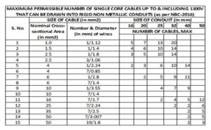
6.10.3 Conduit Wiring System with Rigid Non-Metallic Conduits
Rigid non-metallic conduits are used for concealed conduit wiring.
6.10.3.1 Type and size
All non-metallic conduits used shall conform to accepted standards [8-2(38)] and shall be used with the corresponding accessories {see accepted standards [8-2(39)]}. The conduits shall be circular or rectangular cross-sections.
6.10.3.2 Bunching of cables
Conductors of a.c. supply and d.c. supply shall be bunched in separate conduits. For lighting and small power outlet circuits phase segregation in separate circuits is recommended. The number of insulated cables that may be drawn into the conduits are given in Table 1 B. In Table 1B, the space factor does not exceed 40 percent.
TABLE 1B
6.10.3.3 Conduit Joints
Conduits shall be joined by means of couplers. Where there are long runs of straight conduit, inspection type couplers shall be provided at intervals. For conduit fittings and accessories reference may be made to the good practice [8-2(39)].
6.10.3.4 Fixing of conduit in chase
The conduit pipe shall be fixed by means of stapples or by means of non-metallic saddles placed at not more than 800 mm apart or by any other approved means of fixing. Fixing of standard bends or elbows shall be avoided as far as practicable and all curves shall be maintained by sending the conduit pipe itself with a long radius which will permit easy drawing in of conductors. At either side of bends, saddles/stapples shall be fixed at a distance of 150 mm from the centre of bends.
6.10.3.5 Inspection boxes
Suitable inspection boxes to the nearest minimum requirements shall be provided to permit periodical inspection and to facilitate replacement of wires, if necessary. The inspection/junction boxes shall be mounted flush with the wall or ceiling concrete. Where necessary deeper boxes of suitable dimensions shall be used. Suitable ventilating holes shall be provided in the inspection box covers, where required.
6.10.3.6 The outlet boxes such as switch boxes, regulator boxes and their phenolic laminated sheet covers shall be as per requirements of 6.10.1 (h). They shall be mounted flush with the wall.
6.10.3.7 Types of accessories to be used
All accessories such as switches, wall sockets, etc, may be either flush mounting type or of surface mounting type.
6.10.3.8 Bends in conduits
Wherever necessary, bends or diversions may be achieved by bending the conduits or by employing normal bends, inspection bends, inspection boxes, elbows or similar fittings. Heat may be used to soften the conduit for bending and forming joints in case of plain conduits.
6.10.3.9 Outlets
In order to minimize condensation or sweating inside the conduit, all outlets of conduit system shall be properly drained and ventilated, but in such a manner as to prevent the entry of insects.
6.11 Cable Trunking/Cable Ways
Cable trunking and ducting system of insulating material are used for surface wiring. The number of insulated conductors that can be drawn into cable trunking and ducting system are given in Table 2.
TABLE 2
| Maximum Permissible Number of PVC Insulated 650/1100 Grade Aluminum/Copper Cable Confirming to Accepted Standard (8-2(3)) that can be drawn into Cable Trunking /Cable Ways | |||||||
| S. No |
Nominal Cross-Sectional Area of Conductor mm2 |
10/15 mm x 10mm | 20/15 mm x 10mm | 25/15 mm x 16mm | 32mm x 16mm | 40mm x 25mm | 40mm x 40mm |
|
i |
1.5 | 3 | 5 | 6 | 8 | 12 | 18 |
|
ii |
2.5 | 2 | 4 | 5 | 6 | 9 |
15 |
|
iii |
4 | 2 | 3 | 4 | 5 | 8 |
12 |
|
iv |
6 | 2 | 3 | 4 | 6 |
9 |
|
|
v |
10 | 1 | 2 | 3 | 5 |
8 |
|
|
vi |
16 | 1 | 2 | 4 |
6 |
||
|
vii |
25 | 1 | 3 |
5 |
|||
|
viii |
32 | 2 |
4 |
||||
|
ix |
50 | 1 |
3 |
||||
|
x |
70 | 1 |
2 |
||||