
NBC 2016 –
4. Planning of Electrical Installation –
Following topics are covered in this section –
4.1 – General
4.1.1. – The design & planning of an electrical wiring installation
4.2 – Substation & switch Rooms
4.2.2 – Layout of substation
4.2.2.2 – Capacity and size of station
4.3 – Emergency & power back up system
4.3.1 – Location
4.3.2 Room for Emergency Power back up system
4.3.3 Installation & other requirements
4.4 – Location of MV/LV Switch Room other than in substation
4.5 – Location & requirement of Distribution Panels
4.6 – Substation Safety
4.1 – General –
The design & planning of an electrical wiring installation involve considerations of all prevailing conditions and is usually influenced by the type & requirements of the consumer.
Various utility services including LV system namely intercom, data cabling, CCTV, fire alarm shall also be taken into account with anticipated future requirement.
A competent electrical design engineer should be involved at the planning stage for its intended purpose & ensure safety, reliability & energy efficiency.
Electricity is linked to all services and addition of standby & emergency power supply systems adds to the complexity, thus requiring proper coordinated drawing.
The designs should also have to keep the availability of optimum access to installations to ensure proper maintenance.
Considering various utility services & to avoid conflict amongst them, it is most important to estimate space requirement for electrical work including LV system, at planning stage & allocate it in consultation with an architect /civil engineer.
4.1.1. – The design & planning of an electrical wiring installation shall take into consideration the following –
a) Type of supply, building utility, occupancy, envisaged load & the earthing arrangement available.
b) Provisioning of air conditioning systems in present and/or future loading,
c) Climate condition such as cooling air temperature, moisture, or such other conditions which are likely to affect the installation adversely.
d) Possible presence of inflammable or explosive dust, vapour or gas.
e) Degree of electrical & mechanical protection necessary,
f) Importance of continuity pf service including the possible need for standby supply,
g) Probability of need for modification or future extension,
h) Probable operation & maintenance cost taking into account the electricity supply tarrifs available,
j) Relative cost of various alternative methods,
k) Need for radio & telecommunication interference suppression,
m) Ease of maintenance,
n) Safety aspects,
p) Energy conservation,
q) Importance of proper discrimination between prospective devices for continuity of supply & limited isolation of only the affected portion &
r) Reliability of power supply & redundancy (of sources & distribution paths) to cater the needs for emergency power & standby power for continued operations of systems as well as integration of alternate sources of energy as well as integration of alternate sources energy such as diesel generation, solar energy, wind power etc.
4.1.2. – All electrical apparatus shall be suitable for the services these are intended for.
4.1.3. – Coordination –
Proper coordination & collaboration between the architect, civil, engineer, electrical engineer & mechanical engineer shall be affected from the planning stage of the installations. Whenever required, prior approval of drawings shall be taken from concern electrical supplier/electrical inspector.
4.1.4. – Before starting wiring & installation of fittings and accessories, information should be exchanged between the owner of the building/architect/consultant/electrical contractor & the local supply authority in respect of tariffs applicable, types of apparatus that may be connected under each tariff, requirement of space, for installing meters, switches etc & for total load requirements of lights fans & power.
4.1.5. – While planning an installation, consideration should be taken of the anticipated increase in the use of electricity for lighting, utility sockets, heating etc.
For the house-holder who may otherwise may be tempted to carry out extension of the installation himself or to reply upon use of multi-plug adaptors & long flexible cords, both of which are not recommended.
4.2 Substation & Switch rooms –
4.2.1 – Location & other requirements –
The location & other requirements of a substation & switch room is given below –
- Availability of power lines nearby may be kept in view while deciding the location of the substation.
- The substation should preferably be located in a separate utility building & may be adjacent to the generator room, if any. Location of substation in the basement should be avoided as far as possible.
- In case there is only one basement in a building, the substation, the substation/switch room shall not be provided in the basement. Also, the floor level of the station shall not be lowest point of the basement.
- Ideal location of an electrical substation for a group of buildings will be at electrical load center. Generally the load center will be somewhere between the geometrical center and the ac plant room, as ac plant room will normally be the largest load, if the building(s) are centrally air conditioned.
- In order to prevent storm water entering the transformer & switch rooms through the soak pits, the floor level of the substation/switch-room shall be at least 300mm above the highest flood water level that may be anticipated in the locality. Also, facility shall be provided for automatic removal of water.
- Substation shall not be located immediately above or below plumbing water tanks or sewage treatment plant (STP) water tanks at the same location.
- All door openings from substation, electrical rooms etc should open outwards. Vertical shutters (like fire rated rolling shutters) may also be acceptable provided they are combined with a single leaf door opening outwards for exit in case of emergency.
For large substation room/electrical room having multiple equipment, two or more doors shall be provided which shall be remotely located from each other.
- If substation is located at a height 1000m above MSL, then adequate derating of equipment shall be considered.
- In case of HV panel & transformer located at different floors or at a distance more than 20m, HV isolator shall be provided at transformer end.
- In case transformers & main LV/HV panel rooms are located at different floors or at a distance more than 20m, MV/HV isolator shall be provided at transformer end.
In case transformer & main LV/HV panel room are located at different floors, the designer should also take-care of the safety requirements caused lack of direct visibility of the status of the controlling switch. To cater such issue, it may be necessary to provide additional isolator or emergency push button in the vicinity to trip the supply . Decision has to be taken based on the possible risks.
11. No services or ventilation shafts shall open into substation or switch room unless specific to substation or switch room.
12. Oil-filled installations – Substations with oil filled equipment require consideration for fire detection, protection & suppression.
Oil-filled transformer require suitable soak pit with gravity flow to contain the oil in case of spillage from the transformer. Installation of oil-filled equipment shall meet the following requirement –
i) Substations with oil-filled equipment/apparatus (transformer & high voltage panels) shall be either located in open or in a utility building.
They shall not be located in any floor other than the ground floor or the first basement of a utility building. They shall not be located below first basement slab of a utility building.
They shall have direct access from outside the building for operation & maintenance of the equipment.
ii) Substation/Utility buildings (where substation or oil-filled transformer is located) shall be separated from the adjoining building including the main building by at least 6m clear distance to allow passage of fire tender movement between the substation/utility building & adjoining building/main building.
iii) There shall be no interconnecting basement with the main building underneath the oil-filled transformers.
iv) Provision for oil drainage at a point at a lower level & separated by adequate fire barrier shall be provided. If there is a floor directly below the ground floor level or first basement where oil filled Transformer or circuit breakers are placed, they can shall be separated by a fire barrier of appropriate fire rating as per part 4 ‘Fire & life safety’ of the code & proper oil drainage system shall be provided to avoid possible leakage of oil into the lower floor.
v) Substation equipment having more than 2000 ltr of oil whether located indoors in the utility building or outdoors shall be shall have baffle walls of 4 h fire rating between the apparatus (see also part 4 ‘Fire & life safety’ of the code for the fire safety related requirements)
vi) Provision shall be made for suitable oil soak pit, and where use of more than 9000 ltr of oil in any one oil tank, receptacle or chamber is involved, provision shall be made for the draining away or removal of any oil which may leak or escape form the tank, receptacle or chamber containing the same.
Special precautions shall be taken to prevent the spread of any fire resulting from the ignition of the oil from any cause & adequate provision shall be made for extinguishing any fire which may occur.
vii) In respect of all oil type transformers located at basement, a kerb (sill) of a suitable height shall be provided at the entrance in order to prevent the flow of oil from a ruptured transformer into other parts of the basement in the event of the possibility of oil spillage from the transformer on its failure.
viii) Adequate fire barriers or detectors shall be provided to avoid flames from the substation reaching or affecting the upper floors (see also part 4 ‘Fire & life safety’ of the code).
ix) For transformer having large oil content (more than 2000 litre), rule 44(2) of the Central Electricity Authority (Measures relating to Safety & Electric Supply) Regulations, 2010 as amended from time to time shall apply.
13. Dry-type installations – In case electric substation has to be located within the main multi-storeyed building itself for unavoidable reasons, it shall be a dry type installations with very little combustible material such as a dry type transformer with vacuum (or SF6) breakers as HT switchgear and ACB or MCCB as medium voltage (MV) switchgear.
Such substation shall be located on ground level or on first basement and shall have direct access from the outside of the building for operation and maintenance of the equipment.
Exceptionally, in case of functional buildings, such as air traffic control towers, data centers & buildings of height mare than 100m having high electrical load requirement, dry type installations/substations may also be provided. This measure will decrease the current flow & short circuit rating at various points, thereby reducing vulnerability to fire. In such cases, a base substation shall be located at ground floor/first basement to cater the main MV/LV panel which feed life & safety services loads as defined in 4.2.1(29). The base substation shall be located in such a way to provide direct access to the firemen in case of any emergency. The power supply control to any substation or transformer located at upper floors shall be from the base substation so that in case of fire, electrical supply can be easily disconnected to avoid additional losses.
14. The power supply HV cables voltage shall not be more than 12KV & a separate dedicated & fire compartmented shaft shall be provided for carrying such high voltage cables to upper floors in the building. These shall not be mixed with any other shaft & suitable fire detection & suppression measures shall be provided throughout the length of the cable on each floor.
- The provision for installation & removal of substation equipment should be provided from inside or outside the building without disturbing the associated major equipment in the substation.
- In case of compact substation (see accepted standard 8-2(4)), design & location of the station shall ensure safety of the people around the compact substation installed along walkways, playgrounds, etc.
Compact substation with incomer voltage of 12KV or less, when located in open areas shall have fencing or barrier (of any metal based protection, such as wire mesh or chain link, which is duly earthed) against unauthorized contact possibility around it at a minimum distance of 750mm around it with access for maintenance from all sides. For incomer voltage more than 12KV & less than 2KV the fencing distance from substation may be 1000mm minimum. In case of more than 24KV incomer, the distance may be further increased accordingly. The fencing design take care of the servicing & maintenance requirements of the substation equipment.
17. In case of two transformers (dry type or transformers with oil quantity less than 2000 litre) located next to each other without intermittent wall, the distance between the two shall be minimum 1500mm for 11KV, minimum 2000mm for 22KV and minimum 2500mm for 33KV, Beyond 33KV, two transformers shall be separated by a baffle wall of 4 h fire rating.
- Horizontal routing of HT cable through functional/occupied areas should be avoided in view of safety.
- If dry type transformer is used, it may be located adjacent to medium voltage switchgear in the form of unit type substation. In such a case, no separate room or fire barrier for transformer is required either between transformers or between transformer & switchgear, thereby decreasing the room type the room space requirement; however minimum distances as specified in 4.2.1 (17) shall be maintained between the apparatus depending upon voltage ratings. Layout of equipment should take care of the need that any one piece of the equipment or subassembly can be taken out of service and out of the installed location, while keeping the remaining system in service. Working space for access for maintenance of equipment, while keeping an adjoining section of the substation live to maintain power supply to essential loads, may require additional space between such sections of equipment.
- In places where flooding can occur & water level may go above 1000mm, the base substation may be located on one level above the ground level of a utility building. In such cases, one feeder should feed ground level & levels below with automatic tripping of the feeder to avoid electrocution in case of live electricity coming in contact with water.
Designer shall use their discretion in special cases & depending on the degree of reliability, redundancy & the category of load & make suitable provisions.
(Note- In cases, where the substation is located one level above ground level of utility building, this should be after due evaluation of other risks posed such a location combined with the concurrence for such a decision from State Electricity Authority comprising the electrical inspectorate & the distribution licensee & the fir service).
21. For acoustical enclosure/treatment reference may be made to part 8 ‘Building Services’, Section 4 ‘Acoustics, Sound Insulation & Noise Control’ of the Code.
22. Minimum recommended spacing between walls & the transformer periphery from the point of proper ventilation shall be in accordance with the good practice (8-2(9)) (see also Fig1A). The actual spacing may be different than those given in the figure, depending on the circumstances, such as access to the accessories. Other requirements relating to the installations of the transformers shall be in accordance with the good practice (8-2(9)).
23. High voltage switch room/ space – The designing should take care of HV equipment space & clearances required around for maintenance & personnel safety as given 5.3.6.8. This room may preferably have direct access from outside.
In case of substation having one transformer & one source of supply, the owner shall provide one high voltage switch.
In case of single point supply with two or more transformers, the number of switch required will be one for incoming supply & one for each transformer.
Additional space may be provided keeping in mind future requirement, if any. In case of duplicate supply two switches shall be provided with mechanical/electrical interlocking arrangement. In case the number of incoming and outgoing switches exceed five, bus coupler of suitable capacity should invariably be provided.
24. Medium voltage switch room/ space – The floor area required in respect of medium voltage switchgear may be determined keeping in view the number and type of incoming/outgoing bus coupler switches including likely expansion in future & space requirement as given in 5.3.6.8. The additional requirements of MV switch room when located separate from the substation shall be as per 4.2.4.
25. Other requirements relating to installations of switchgears & control gears as given in good practice (8-2(10)) shall also be compiled with.
26. The minimum height of substation room/HV switch room/MV switch room shall be arrived at considering 1200mm clearance requirement from top of the equipment to the below of the soffit of the beam (see also Annex C).In case of cable entry /exit is from above the equipment (transformer, HV & MV switchgear), height of substation room/HV switch room/MV switch room shall also take into account requirement of space for turning radius of cable above the equipment height.
27. All the rooms shall be provided with partitions up to the ceiling & shall have proper ventilation. Special care should be taken to dissipate transformer heat & where necessary fresh air louvers at lower level & exhaust fans at higher level shall be provided at suitable locations.
28. In case of cable each trench in substation room/HV switch room/MV switch room, the same shall be adequately drained to ensure to ensure no water is stagnated at any time with the live cables.
29. Power supply Emergency fire & life safety system – Emergency power supplying distribution system for critical requirement for functioning of fire & life safety system & equipment, shall be planned for efficient & reliable power & control supply to the following system & equipment where provided,
i) Fire pumps;
ii) Pressurizing & smoke venting; including its ancillary systems such as dampers & actuators;
iii) Fireman’s lifts (including all lifts);
iv) Exit signage lighting;
v) Emergency lighting;
vi) Fire alarm system,
vii) Public Address (PA) system (relating to emergency voice evacuation & announcement);
viii) Magnetic door hold open devices; and
ix) Lighting in fire command center & security room.
Power supply to these systems & equipment shall be from normal & emergency (standby generator) power sources with changeover facility. It shall be ensured that in case of the power supply is from HT source/HT generation transformers should be planned in standby capacity to ensure continuity of power to such systems. Whereever transformers are installed at higher levels in the buildings and the back up GD sets are of higher voltage rating, then dual redundant cables shall be taken to all transformers. The generator shall be capable of taking starting current of all the fire & life safety systems & equipment as above. Where parallel HV/LV supply from a separate substation fed from different grid is provided with appropriate transformer for emergency, the provision of generator me be waived in consultation with authority.
The power supply to the panel/distribution board of these fire & life safety systems shall be through fire proof enclosures or circuit integrity cables or through alternate route in the adjoining fire compartment to ensure that supply of power is reliable to these systems and equipment. It is to be ensured that the cabling from the adjoining fire compartment is to be protected within the compartment of vulnerability. The location of the panel/distribution board feeding the fire and life safety system shall be in fire safe zone ensuring supply of power to these systems.
Cables for fire alarm & PA system shall be held in metal conduits or armoured to provide physical segregation from the power cables.
30. Other requirements as given in Central Electricity Authority (measures relating to safety & Electricity Supply) Regulations, 2010 as amended shall also be complied with. The fire safety requirements of substations enclosures, that is walls, floor, ceiling, openings, doors etc as given in Part 4 ‘Fire and Life Safety’ of the Code shall also be complied.
The fire safety requirements for substation and electrical rooms, including fire rating requirements of substations enclosure, that is, walls, floor, ceiling, openings, doors, etc as given in part-4 “Fire and Life Safety” of the code shall also be complied with.
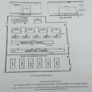
4.2.2 – Layout of substation –
4.2.2.1. The flow of power is from supply company’s meter to HV room, then to transformer and finally to MV switchgear room.
- The layout of the room & trenches of required depth shall be in accordance with this flow, so optimize the cables, bus trunking, etc.
- Visibility of equipment controlled from the operating point of the controlling switchgear is also a desirable feature, though it may not be achievable in case of large substations.
- Substations should not be located at of across expansion joints.
- The room/space required in a substation shall be provided as given below –
- a. Supply company’s meter room, generally at the periphery of the premises with direct access from the road/outside,
- b. HV isolation room, required in case the substation is away from meter room & is planned adjustment to meter room for disconnecting supply in case of any repair required between meter room & substation.
- c. HV panel room/space, located adjacent to transformer,
- d. Transformer room/space, separate space in case of oil filled transformer and combined space in case of dry type transformer.
- e.MV isolation room/space, required in case MV panel is away from transformer or on a different level for isolating supply in case of any repair required between transformer & MV switchgear, and
- f. Main MV panel room/space, required for distribution to different facility/utility in a building. Atypical layout of substation is shown in fig given below –
4.2.2.2 Capacity and size of station –
- The capacity of a substation depends upon the area of the building and its type.
- The capacity of substation may be determined based on the load requirements (see also 3.3).
- Rating of electrical equipment as given in 1, may be assumed, unless the values are known or specified and diversity requirements as given below may be used for load assessment:
| S. No | Purpose of final circuit fed from conductors or switchgears to diversity applies | Typical allowances for diversity based on;
Type of building |
||
| Individual house hold installations, individual dwelling of a block | Small shops, stores, offices & business premises | Small hotels, boarding houses etc. | ||
| (1) | (2) | (3) | (4) | (5) |
| i) | Lighting | 66% of total current demand | 90% of total current demand | 75% of total current demand |
| ii) | Heating & power | 100% of total current demand up to 10A + 50% of any current demand in excess of 10A | 100% full load current of largest appliances + 75% of remaining appliances | 100% full load current of largest appliances + 80% of second largest appliances + 60% of remaining appliances |
| iii) | Cooking appliances | 10A + 30% full load of connected cooking appliances in excess of 10A + 6A if socket outlet incorporated in the unit. | 100% full load current of largest appliances + 80% of second largest appliances + 60% of remaining appliances | 100% full load current of largest appliances + 80% of second largest appliances + 60% of remaining appliances |
| iv) | Motors (other than lift motors which are subject to special consideration) | 100% full load current of largest motor + 80% of second largest motor + 60% of remaining motors | 100% full load current of largest motor + 50% of remaining motors | |
| v) | Water heaters (instantaneous type) | 100% full load current of largest appliances + 100% of second largest appliances + 25% of remaining appliances | 100% full load current of largest appliances + 100% of second largest appliances + 25% of remaining appliances | 100% full load current of largest appliances + 100% of second largest appliances + 25% of remaining appliances |
| vi) | Water heaters (thermostatically controlled) | No diversity allowable | ||
| vii) | Floor warming installations | No diversity allowable | ||
| viii) | Water heaters thermal storage space heating installations | No diversity allowable | ||
| ix) | Special arrangements of final circuits in accordance with good practice (8-2(11)) | 100% of the current demand of the largest circuit + 40% of current demand of every other circuit | 100% of the current demand of the largest circuit + 50% of current demand of every other circuit | |
| x) | Socket outlets other than those included Sl No (ix) & stationary equipment other than those listed above | 100% of the current demand of the largest point + 40% of current demand of every other point | 100% of the current demand of the largest point + 75% of current demand of every other point | 100% of the current demand of the largest point + 75% of the current demand of every point is main rooms (dining rooms etc) + 40% of current demand of every other point |
After calculating he electrical load on the above basis , overall load factor of 70 to 90%is to be applied to active at the minimum capacity of substation. A future load may also be considered for substation sizing (see 3.3) .
The area required for substation & transformer room for different capacities is given in annex-C for general guidance. For reliability it is recommended to split the load into more than one transformer and also provide for standby transformer as ell as multiple sources, bus-sections etc.
4.3 EMERGNCY POWER BACK UP SYSTEM –
4.3.1 Location –
The emergency power supply (such as generating sets) should not be allowed to be installed above ground floor or below first basement level of the building.
In case of DG sets located in basement, the ceiling of the DG room shall be ground floor slab.
It is preferable to install the standby generator in utility building. If installed in the enclosed space, facilities for forced ventilation shall be provided such that there is minimum derating of the equipment.
The generating sets should preferably be housed adjacent to MV switchgear in the substation building to enable to transfer of electrical load efficiently and also to avoid transfer of vibration and noise to the main building.
4.3.2 Room for Emergency Power back up system –
- The capacity of standby generating set shall be sized for emergency fire & lift safety systems (see 4.2.1 (29)) and other utilities as required and identified for functional requirement of the building.
- Having chosen the capacity & number of generating sets, required space may be provided for their installations (see annex D for general guidelines).
- There shall be provision of separate direct escape & entry direct from outside so that in case of fire, electrical supplies can be disconnected to avoid additional losses which may be caused due to electrical supply, present at the time of fire.
- The height of DG set rooms shall however be more than 3000mm above the GDs set height unless required to the DG room ventilation requirements.
- Adequate space shall be provided for storing of fuel.
- Facilities’ including space at appropriate positions, relative to the installed equipment has to be kept in the layout design for removal of equipment or sub-assemblies for repair & maintenance.
- When it is located at a place, other than the ground level with direct equipment access, a hatch or ramp shall be provided.
4.3.3 Installation & other requirements –
Following installation & other requirement shall also be complied with –
a) Day oil tanks for the DG sets shall be complied with “The Petroleum Act, 1934”.
b) The emergency installation shall comply with the norms laid down by the CPCB (Central Pollution Control Board) & shall also be in compliance with “The Petroleum Act, 1934” & guidelines of OISD (Oil Industry Safety Directorate).
Compartmentation for fire protection with detection and first aid protection measures is essential.
(Note- Different types of fire safety requirements exists for the diesel engine & generator for the oil storage area & for the switchgear (see also part -4 ‘Fire & life safety of the code’.)
c) Acoustic enclosure of DG sets / acoustic lining of DG room & ventilation system for DG room shall be in line with the requirement of CPCB.
If DG set is located outdoors, it shall be housed in acoustics enclosure as per the requirement of CPCB norms.
For acoustical enclosures/treatment reference shall also be made to part 8 ‘ Building Services, Section -4 Acoustic, Sound Insulation & Noise Control’.
d) The generator house should have proper ventilation for engine combustion requirements and as well as for the body heat removal from radiator or cooling tower, fire- fighting equipment, etc.
The other requirements given in part-4 ‘ Fire & Life Safety ‘ of the code for room for emergency power back up system including DG set room shall also be complied with.
e) Other environmental requirements under the provisions of Environment Protection Rules, 1986 and norms laid down by CPCB, as amended from time to time shall be taken into account particularly from the aspect of emissions including the height of exhaust pipe & permitted noise levels/controls.
4.4 Location of MV/LV Switch Room other than in substation–
- In large installations other than where a substation is provided, a separate switch room shall be provided, this shall be located as close the electrical load center as possible on the ground floor or on the first basement level of the building.
- Suitable cable trays shall be laid with minimum number of bends from the point of entry of the main supply cable to the position of the main switchgear.
- The switch room shall also be placed in such a position that riser shafts may readily be provided therefrom to the upper floors of the building in one straight vertical run.
- In larger buildings, more than one riser shaft may be required & then horizontal trays may also be required, for running cables from the switch room to the foot of each rising main.
- Such cable trays shall either be reserved for specific voltage grades or provided with a means of segregation for medium, low & extra low voltage installations such as call bell system, telephone installations, fire detection and alarm system, security system, data cables, announcement or public address system.
(Cables/wires for emergency fire & life safety fire services & their routing shall be in accordance with 4.2.1(29) and part 4 ‘Fire & Life Safety’ of the code so that these services are maintained even in case of a fire).
4.5 Location & requirement of Distribution Panels-
All distribution panel, switchgears shall be installed in readily accessible position. The electrical control gear distribution panels and other apparatus, which are required on each floor may conveniently be mounted adjacent to the rising mains, and adequate space considering clearances required as per 5.3.6.8 shall be provided at each floor for this purpose.
4.6 Substation Safety –
The owner & the operator of any substation shall be collectively & severally be responsible for any lapse or neglect leading to an accident or an incidence of an avoidable abnormality & shall take care of the following safety requirements:
a) Enclose the substation or similar equipment where necessary to prevent, so far as is responsibly practicable, danger of electric shock or unauthorized access.
b) Enclose any part of substation which is open to the air, with a fence (earthed efficiently at both ends) or wall not less than 1800mm (preferably not less than 2400mm) is height, to prevent, so far is responsibly practicable, danger of electric shock or unauthorized access.
c) Ensure that there are at all times displayed,
- Sufficient safety signs of such size and placed in such positions as are necessary to give due warning of such danger as is reasonably foreseeable in the circumstances;
- A notice which is placed in a conspicuous position and which gives the location or identification of the substation equipment, the name of each generator distributor who owns or operates the substation and the telephone where is a suitably qualified person appointed for this purpose by the generator or distributor will be in constant attendance; and
- Such other signs, which are of such size and placed in such positions, as are necessary to give due warning of danger having regard to the sitting of, the nature of, and the measures taken to ensure the physical security of, the substation equipment;
d) Take all reasonable precautions to minimize the risk of fire associated with equipment; and
e) Ensure that, in addition to provisions mentioned in (c), name and emergency telephone number of the authorized personnel shall also be displayed at the substations and instructions covering schematic diagram; requirements of switchgear interlocking, if any; and permission requirements, if any, for load limitations on (incoming ) feeders; be also prominently displayed.