
Electrical Power
What is Electrical Power: Definition of electric power is given below –
Definition –
Electric power is the rate at which electric energy is transferred by an electric circuit. The unit of power is the watt, one joule per second. Electric power is usually produced by electric generators, but can also be produced by other sources such as wind power, solar power, hydro power, etc. The value of power depends on supply voltage, current, resistance, reactance, impedance, power factor etc.
Electrical Power Formula / Calculation of Electrical Power –
Let us understand electrical power in DC & AC system/circuits.
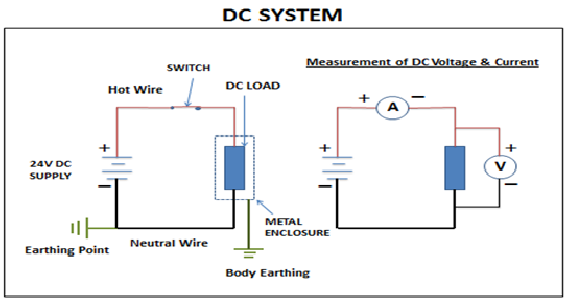
A – Power in DC Circuits –
Power in a DC circuit is calculated by – P =V I
Power in a DC circuit is calculated by – P = I²R(where V = IR)
Power in a DC circuit is calculated by – P = V²/R(where I = V/R)
Where P = Power in watts, V= Voltage in V & I = Current in Amp & R is the resistance.
(Note: In DC system, load shows only resistive behavior when DC supply is applied to the load because DC supply doesn’t change with time).
(Note – A DC load can’t be used on AC supply vice versa.)
B – Power in AC Circuits –
There are two types of power used in AC system – 1) Single phase & 2) Three Phase. Normally electrical power is generated by the generating plants. Type of power depends on type of supply e.g. Single phase power needs single phase supply & three phase power needs three phase supply. 3 Phase power can be used for three phase load as well as single phase load. 3 phase power is normally used for high capacity 3 phase loads & single phase power is used for small electrical loads.
A –Power in single phase Circuit –
Power in 1- phase electrical system – P = VI CosØ or Vph IphCosØ
Power in 1- phase electrical system – P = Iph²ZCosØ (where Vph = IphZ)
Power in 1- phase electrical system – P = Vph² / ZCosØ (Where Iph = Vph/Z)
Where P = Power in watts, Iph = phase current, Vph = phase voltage, CosØ = Power Factor& Z = Impedance.
In single phase supply, the value of voltage is 230V.
(Note– In ac system, load offers resistive, inductive & capacitive behavior which depends on the type of load. The overall effect of above behavior is called impedance. The above behavior is because of AC supply which varies with time. While in DC system, load offers only resistive behavior.)
B – Power in 3 phase Circuit –
Power in 3- phase electrical system –P = Г3 VL X IL X CosØ,
Power in 3- phase electrical system – P = 3 Vph X Iph X CosØ,
where VL = Line Voltage, IL = Line Current, CosØ = Power Factor,
where Vph = Phase Voltage, Iph = Phase Current, CosØ = Power Factor,
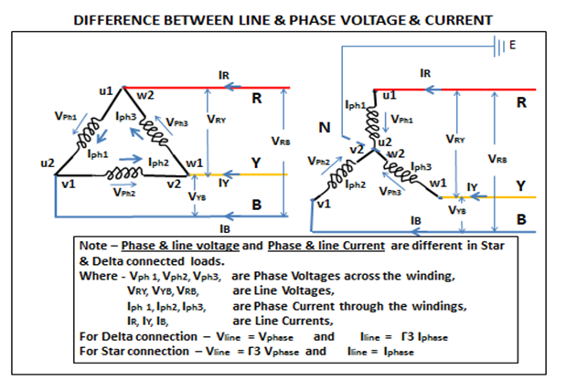
LINE & PHASE VOLTAGE /CURRENT –
In 3- phase circuit there are two terms which generally used – Line voltage & phase voltage& Current. Let us understand both terms.
Line Voltage–
It is a voltage which is measured between two lines such as between R&Y, Y&B & RB.
Phase Voltage –
It is a voltage which is across the winding such as Vph1, Vph2& Vph3.
Line Current –
It is a current which flows through the line like IR, Iy& IB
Phase Current –
It is a current which flows through winding such as Iph1, Iph2& Iph3.
Now clearly we can see (through diagram) that voltage & current in delta & star connections are not same.
Frequently Asked Questions (FAQs) on Electrical Power-
Q1) What is Electrical Power system
Ans) Electrical power system is network of electrical equipment (such as generators, transformers, relays, circuit breakers etc), transmission lines, distribution lines which are responsible to generate, transmit & distribute electrical power to the users.
Broadly two types of electrical power system available – 1) Govt electrical power System which is installed by the govt for its citizens, industries & commercial requirement & 2) Private electrical power system which is installed by the industries or large commercial complexes to meet the power requirement.
An electrical power system has three major parts – generation, transmission & distribution.
Generation – Electrical power is generated by power plants which may be a thermal power plant, hydro power plant, atomic Power plant, solar power plant, wind power plant etc where electricity is produced.
Transmission – Once electricity is generated, this needs to be transferred to users & this is done with help of transmission lines. Transmission of power is done through overhead wires at very high voltage which helps to reduce transmission cost & energy losses.
Distribution – The function of distribution system is to receive transmitted power & distribute it to the consumer. This is done with the help of substation & distribution overhead lines. Substation is a place where high voltage power is reduced with stepdown transformers & this reduced power is supplied to different – different parts of the city through network of overhead lines. Normally these substations are installed outside the cities.
Q2) What is electrical power stations
Ans) Electrical substation is a part of electrical power system which is used for different purposes e.g it is used with generating plant where it is used for transmission of power, it is used for distribution purpose also power is reduced to low voltage, it used for diverting the power one location to another location or multiple locations as per systems requirement.
Complete detail Electrical Substation is given on a separate page of this website.
Q3) How to calculate electrical power
Ans) Electrical power is calculated with help of formulas which are given in above section of this page.
Q4) Electrical power measured in what?
Ans) It is measured in Watts.
Q5) Electrical power components & system?
Ans) The main components of electrical power system are – generators, step-up transformers, protection relays, circuit breakers, transmission lines, stepdown transformers, distribution lines and electrical load. Each component plays a very important role in the system –
Generators – The role of generator is to produce electricity which is produced at specific voltage let’s say- 11KV.
Step-up Transformer – Transformers are installed in the substation from where voltage is stepped up & transfer. The function of step-up transformer is to increase the generated voltage to high or very high voltage (depending on the distance where this power is to be generated). This increased voltage may be 66KV, 110KV, 220KV, 440KV, 750KV. The purpose of transferring power at higher voltage is to reduce the line losses (such as I2R losses & Voltage drop) because when voltage increases, the current decreases in the line. We can understand from following formula of power –
P = V * I or I = P / V or I α 1/V (When power is constant or same value of power)
Above relation shows that Current, I value will decrease when value of voltage, V will increase.
Protection Relays – Different types of protection relays are installed in the substations to protect the transformers & transmission lines from various faults such as short circuit, overloading, earth fault & faults related with transformer’s oil etc). These relays sense the fault & give tripping command to circuit breakers.
Circuit Breakers – Circuit breakers are switching devices & installed in substations. The function of breaker is to isolate / cut the electrical supply manually / remotely / on fault.
Transmission lines – Power from substation is transferred through transmission lines to different parts of country. These overhead lines which are supported by metal structures called towers. High voltage lines are very dangerous because of its high value. The power is transferred through 3 wire system (R,Y,B) from generating substation to distribution substation. Distribution substations are located outsides the city where voltage of power is reduced & distributed across the city for various utilizations.
Stepdown Transformers- The power which is utilized by the load is reduced to low voltage level by stepdown transformers which are installed in substations located outside of the city (Note- in some cases substations are located inside the large cities also.) The substations which have stepdown transformers, also have protection relays & circuit breakers for protection & switching of transformers, distribution lines etc.
Distribution lines – The power distribution to the load is done at low voltage which be 33KV, 11Kv & 415V. Generally, 33KV & 11KVa supply are used for industrial /commercial purpose while 11KV & 415V are used for residential purpose where 11KV & 415V lines are distributed in the city/town/village etc. where 11LV is given to large establishments while 415V & 230V is given for domestic purpose. This distribution is done through state distribution companies.